This library was written between 2009 and 2013. I decided to publish my work in order to let others to finish it. Unfortunately human nature is lazy and other people only want you to make profit with your work.
Are you going to pay me for finishing this work??? |
Friday, 17 January 2020
Master functions in Function code 1 ,2 and 15 still not implemented.Why? #29
I've been looking at my code Issues in GitHub and there was a funny issue there:
Sunday, 31 March 2019
How to change program for Serial 1 port on Arduino Mega?
When the Modbus object is being declared,
/**
 *  Modbus object declaration
 *  u8id : node id = 0 for master, = 1..247 for slave
 *  u8serno : serial port (use 0 for Serial)
 *  u8txenpin : 0 for RS-232 and USB-FTDI
 *               or any pin number > 1 for RS-485
 */
Modbus slave(1,0,0); // this is slave @1 and RS-232 or USB-FTDI
You should replace it and write:
Modbus slave(1,1,0); // this is slave @1 at Serial1 and RS-232 or USB-FTDI
If you need to use Serial2 or Serial3, just put a 2 or a 3.Monday, 25 February 2019
How work with two slaves
This comes from Github:
Hello! I can not understand and in the examples there is no option when the master works with two or more slave devices. If there are examples - I will be grateful for the help.
And my answer:
Hi,
As a "quick and dirty" example, I would suggest you to modify the current advanced Master and declare the second telegram for another slave:
// telegram 0: read registers
telegram[0].u8id = 1; // slave address
telegram[0].u8fct = 3; // function code (this one is registers read)
telegram[0].u16RegAdd = 0; // start address in slave
telegram[0].u16CoilsNo = 4; // number of elements (coils or registers) to read
telegram[0].au16reg = au16data; // pointer to a memory array in the Arduino
// telegram 1: read a single register from another slave
telegram[1].u8id = 2; // another slave address
telegram[1].u8fct = 3 // function code
telegram[1].u16RegAdd = 0; // start address in slave
telegram[1].u16CoilsNo = 4; // number of elements (coils or registers) to read
telegram[1].au16reg = au16data+4; // pointer to a memory array in the Arduino
The rest of the code would be the same.
Sunday, 30 April 2017
Serial Data Monitor
I've received a couple of questions in the Github regarding to debugging applications with this Library and the Serial Data Monitor.
The Arduino Serial Monitor shows ASCII data. As you know, the Modbus RTU protocol handles raw binary data. Therefore it only shows ⬜ and wrong symbols instead of the real values.
I'm having the same problem. To my knowledge the response from the modbus slave device is processed by the function get_FC3 which moves them from the au8buffer to au16reg however I am struggling to get data from them. I used a 3rd party program to ensure I am getting the correct query from my arduino and Ive used the same program to send that query to the modbus device and received the expected response. So I know the data is there I am just having some issues displaying them.
The Arduino Serial Monitor shows ASCII data. As you know, the Modbus RTU protocol handles raw binary data. Therefore it only shows ⬜ and wrong symbols instead of the real values.
When I wrote this library, I used third-party simulators either for the Master or for the Slave. I recommend you these:
QModbus: http://qmodbus.sourceforge.net/
Modpoll and its slave Variant: http://www.modbusdriver.com/modpoll.html
Sunday, 21 February 2016
Data frame settings for serial communication
To know more about this subject, please refer to this site.
Arduino Serial library supports several data frames apart from the common 8N1. This is accomplished through the begin method. This is fully discussed in the previous link.
I've modified my library in order to support this. There is also a new example for an Slave, which has 19200 baud, 8 data bits, even parity plus 1 stop bit.
This is exactly the same for a Modbus Master.
/**
 *  Modbus slave example 2:
 *  The purpose of this example is to link a data array
 *  from the Arduino to an external device.
 *
 *  Recommended Modbus Master: modpoll
 *  http://www.modbusdriver.com/modpoll.html
 */

#include <ModbusRtu.h>

// data array for modbus network sharing
uint16_t au16data[16] = {
  3, 1415, 9265, 4, 2, 7182, 28182, 8, 0, 0, 0, 0, 0, 0, 1, -1 };

/**
 *  Modbus object declaration
 *  u8id : node id = 0 for master, = 1..247 for slave
 *  u8serno : serial port (use 0 for Serial)
 *  u8txenpin : 0 for RS-232 and USB-FTDI
 *               or any pin number > 1 for RS-485
 */
Modbus slave(1,0,0); // this is slave @1 and RS-232 or USB-FTDI

void setup() {
  slave.begin( 19200, SERIAL_8E1 ); // 19200 baud, 8-bits, even, 1-bit stop
}

void loop() {
  slave.poll( au16data, 16 );
}
Saturday, 16 January 2016
RS-485 Implementation on an Arduino
RS-485 Standard
The RS-485 allows to implement a low-cost network for several devices. The aim of this post is not to copy the information gathered by Wikipedia regarding RS-485.The RS-485 is a half-duplex protocol, so this means that its devices cannot listen and speak at the same time. The RS-422 is a protocol based on RS-485 that allows this.
Wiring RS-485
Anyway the RS-485 allows to connect several devices with only 3-wires:- Data+ (non-inverting)
- Data- (inverting)
- GND (ground or voltage reference)
Its important to use the GND wire to make use that Data+ and Data- are refered along the network.
It is important to add bias 120 ohm resistors between Data+ and Data- at both edges of the network, when designing bus type networks. In star type networks, I use to install them on the longest arms.
Before starting
- The Arduino based on the ATMEGA328 has only an UART.
- Its UART is used for programming purposes.
- This UART may also be used for RS-485 communication taking some precautions.
How to implement it on an Arduino 328
RS485 transceivers

The MAX485 family is a very popular set of RS485 transceivers, but there are others like those from Texas Instruments or Linear Technology.
An RS-485 typical transceiver consists on the next pins:
- RO is a TTL output to be connected to the microcontroller RxD pin.
- DI is a TTL input to be connected to the microcontroller TxD pin.
- RE and DE use to be connected together and are used for the flow control: At high level RO is at high impedance and at low level RO sends everything broadcasted from the RS-485 side.
- A (Data+) and B (Data-) are connected to the network side.
Simplest Arduino implementation
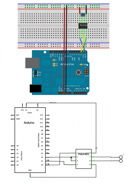
This is the simplest implementation for RS-485 on an Arduino. Its only drawback is that RO interferes with the USB transceiver, unless D2 is at High level to put RO at high impedance.
The UNO and duemilianove include a 10K-ohm resistor in series between D0 and the FTDI chip to allow to mount other devices to the UART. Unfortunatelly the USB port is lost, unless reprogramming the Arduino.
The Modbus port
The Modbus library implements the RS-485. One of the Modbus constructors is declared as:Modbus(uint8_t u8id, uint8_t u8serno, uint8_t u8txenpin);
where
u8txenpin may be an Arduino pin number different of 0. If so, this pin handles the transceiver flow control pins RE/DE. This is automatically done by the Library.
The Modbus library includes an example for an slave:
/**
 *  Modbus slave example 3:
 *  The purpose of this example is to link a data array
 *  from the Arduino to an external device through RS485.
 *
 *  Recommended Modbus Master: QModbus
 *  http://qmodbus.sourceforge.net/
 */

#include <ModbusRtu.h>

// assign the Arduino pin that must be connected to RE-DE RS485 transceiver
#define TXEN 2

// data array for modbus network sharing
uint16_t au16data[16] = {
  3, 1415, 9265, 4, 2, 7182, 28182, 8, 0, 0, 0, 0, 0, 0, 1, -1 };

/**
 *  Modbus object declaration
 *  u8id : node id = 0 for master, = 1..247 for slave
 *  u8serno : serial port (use 0 for Serial)
 *  u8txenpin : 0 for RS-232 and USB-FTDI
 *               or any pin number > 1 for RS-485
 */
Modbus slave(1,0,TXEN); // this is slave @1 and RS-485

void setup() {
  slave.begin( 19200 ); // baud-rate at 19200
}

void loop() {
  slave.poll( au16data, 16 );
}
The slave contains an array au16data, which is available in the RS-485 network either for read or write. Pin 2 is used for the RS-485 flow control.
Monday, 16 February 2015
The library compiles with Arduino IDE v1.6
Very good news! This library also compiles with the lastest Arduino IDE v1.6.0.
http://arduino.cc/en/Main/Software
http://arduino.cc/en/Main/Software
Subscribe to:
Posts (Atom)
I learned your code on GitHub-《Modbus-Master-Slave-for-Arduino》.This work is fantastic,because it uses a lock free delay and almost all functions of Modbus communication are implemented.This is one of the best Arduino library functions I've ever used.Thanks for your contribution.
But I found Master functions in Function code 1 ,2 and 15 still not implemented.Why?What's the trouble with you?
What should I do if I want to implement Function code 2?I would appreciate it if you help me.