Showing posts with label Arduino. Show all posts

Sunday, 21 February 2016

Data frame settings for serial communication

To know more about this subject, please refer to this site.

Arduino Serial library supports several data frames apart from the common 8N1. This is accomplished through the begin method. This is fully discussed in the previous link.

I've modified my library in order to support this. There is also a new example for an Slave, which has 19200 baud, 8 data bits, even parity plus 1 stop bit.

This is exactly the same for a Modbus Master.

/**
 *  Modbus slave example 2:
 *  The purpose of this example is to link a data array
 *  from the Arduino to an external device.
 *
 *  Recommended Modbus Master: modpoll
 *  http://www.modbusdriver.com/modpoll.html
 */

#include <ModbusRtu.h>

// data array for modbus network sharing
uint16_t au16data[16] = {
  3, 1415, 9265, 4, 2, 7182, 28182, 8, 0, 0, 0, 0, 0, 0, 1, -1 };

/**
 *  Modbus object declaration
 *  u8id : node id = 0 for master, = 1..247 for slave
 *  u8serno : serial port (use 0 for Serial)
 *  u8txenpin : 0 for RS-232 and USB-FTDI 
 *               or any pin number > 1 for RS-485
 */
Modbus slave(1,0,0); // this is slave @1 and RS-232 or USB-FTDI

void setup() {
  slave.begin( 19200, SERIAL_8E1 ); // 19200 baud, 8-bits, even, 1-bit stop
}

void loop() {
  slave.poll( au16data, 16 );
} 


Saturday, 16 January 2016

RS-485 Implementation on an Arduino

RS-485 Standard

The RS-485 allows to implement a low-cost network for several devices. The aim of this post is not to copy the information gathered by Wikipedia regarding RS-485.

The RS-485 is a half-duplex protocol, so this means that its devices cannot listen and speak at the same time. The RS-422 is a protocol based on RS-485 that allows this.

Wiring RS-485

Anyway the RS-485 allows to connect several devices with only 3-wires:
  • Data+ (non-inverting)
  • Data- (inverting)
  • GND (ground or voltage reference)
Some devices mark the Data+ and Data- as B and A. I prefer to call them Data+ and Data-, because this is how they are driven and most PLC manufacturers call them so.

Its important to use the GND wire to make use that Data+ and Data- are refered along the network.

It is important to add bias 120 ohm resistors between Data+ and Data- at both edges of the network, when designing bus type networks. In star type networks, I use to install them on the longest arms.

Before starting

  • The Arduino based on the ATMEGA328 has only an UART.
  • Its UART is used for programming purposes.
  • This UART may also be used for RS-485 communication taking some precautions.

How to implement it on an Arduino 328

RS485 transceivers


The MAX485 family is a very popular set of RS485 transceivers, but there are others like those from Texas Instruments or Linear Technology.

An RS-485 typical transceiver consists on the next pins:
  • RO is a TTL output to be connected to the microcontroller RxD pin.
  • DI is a TTL input to be connected to the microcontroller TxD pin.
  • RE and DE use to be connected together and are used for the flow control: At high level RO is at high impedance and at low level RO sends everything broadcasted from the RS-485 side.
  • A (Data+) and B (Data-) are connected to the network side.

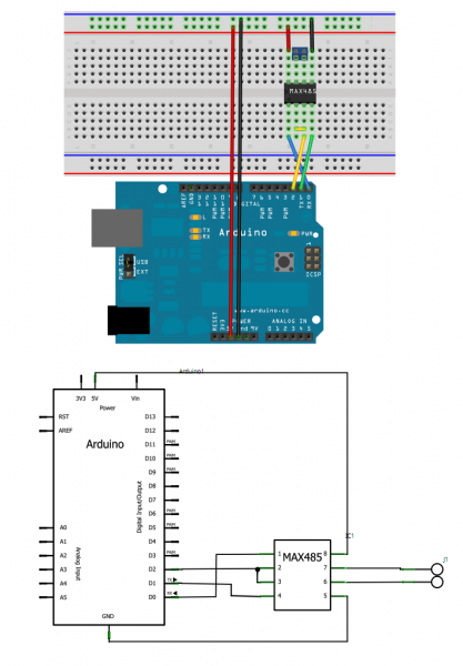
Simplest Arduino implementation

This schematic is borrowed from here.

This is the simplest implementation for RS-485 on an Arduino. Its only drawback is that RO interferes with the USB transceiver, unless D2 is at High level to put RO at high impedance.

The UNO and duemilianove include a 10K-ohm resistor in series between D0 and the FTDI chip to allow to mount other devices to the UART. Unfortunatelly the USB port is lost, unless reprogramming the Arduino.

The Modbus port

The Modbus library implements the RS-485. One of the Modbus constructors is declared as:

Modbus(uint8_t u8id, uint8_t u8serno, uint8_t u8txenpin);

where

u8txenpin may be an Arduino pin number different of 0. If so, this pin handles the transceiver flow control pins RE/DE. This is automatically done by the Library.

The Modbus library includes an example for an slave:

/**
 *  Modbus slave example 3:
 *  The purpose of this example is to link a data array
 *  from the Arduino to an external device through RS485.
 *
 *  Recommended Modbus Master: QModbus
 *  http://qmodbus.sourceforge.net/
 */

#include <ModbusRtu.h>

// assign the Arduino pin that must be connected to RE-DE RS485 transceiver
#define TXEN 2 

// data array for modbus network sharing
uint16_t au16data[16] = {
  3, 1415, 9265, 4, 2, 7182, 28182, 8, 0, 0, 0, 0, 0, 0, 1, -1 };

/**
 *  Modbus object declaration
 *  u8id : node id = 0 for master, = 1..247 for slave
 *  u8serno : serial port (use 0 for Serial)
 *  u8txenpin : 0 for RS-232 and USB-FTDI 
 *               or any pin number > 1 for RS-485
 */
Modbus slave(1,0,TXEN); // this is slave @1 and RS-485

void setup() {
  slave.begin( 19200 ); // baud-rate at 19200
}

void loop() {
  slave.poll( au16data, 16 );
} 
 
The slave contains an array au16data, which is available in the RS-485 network either for read or write. Pin 2 is used for the RS-485 flow control.

Sunday, 14 September 2014

Modbus Master implementation

In my last post, I've published my last Arduino Modbus library, which contains a Modbus Master example:

/**
 *  Modbus master example 1:
 *  The purpose of this example is to query an array of data
 *  from an external Modbus slave device. 
 *  The link media can be USB or RS232.
 *
 *  Recommended Modbus slave: 
 *  diagslave http://www.modbusdriver.com/diagslave.html
 *
 *  In a Linux box, run 
 *  "./diagslave /dev/ttyUSB0 -b 19200 -d 8 -s 1 -p none -m rtu -a 1"
 *  This is:
 *   serial port /dev/ttyUSB0 at 19200 baud 8N1
 *  RTU mode and address @1
 */

#include <ModbusRtu.h>

// data array for modbus network sharing
uint16_t au16data[16];
uint8_t u8state;

/**
 *  Modbus object declaration
 *  u8id : node id = 0 for master, = 1..247 for slave
 *  u8serno : serial port (use 0 for Serial)
 *  u8txenpin : 0 for RS-232 and USB-FTDI 
 *               or any pin number > 1 for RS-485
 */
Modbus master(0,0,0); // this is master and RS-232 or USB-FTDI

/**
 * This is an structe which contains a query to an slave device
 */
modbus_t telegram;

unsigned long u32wait;

void setup() {
  master.begin( 19200 ); // baud-rate at 19200
  master.setTimeOut( 2000 ); // if there is no answer in 2000 ms, roll over
  u32wait = millis() + 1000;
  u8state = 0; 
}

void loop() {
  switch( u8state ) {
  case 0: 
    if (millis() > u32wait) u8state++; // wait state
    break;
  case 1: 
    telegram.u8id = 1; // slave address
    telegram.u8fct = 3; // function code (this one is registers read)
    telegram.u16RegAdd = 1; // start address in slave
    telegram.u16CoilsNo = 4; // number of elements (coils or registers) to read
    telegram.au16reg = au16data; // pointer to a memory array in the Arduino

    master.query( telegram ); // send query (only once)
    u8state++;
    break;
  case 2:
    master.poll(); // check incoming messages
    if (master.getState() == COM_IDLE) {
      u8state = 0;
      u32wait = millis() + 100; 
    }
    break;
  }
} 

The master requires:
  • A memory array, which is linked to the communication network, and this role is assigned to au16data array.
  • A master object, which sends queries and receives answers through Serial port. This belongs to Modbus class and is assigned to address 0.
  • An object or a set of objects to query, which are modbus_t type;
  • A machine state to make queries and wait for answers in the loop section.

The modbus object

This is the master definition. As in a Modbus slave, there are some parameters to define it:
  • node id u8id is always 0;
  • Serial port u8SerNo must be 0 in an Arduino UNO and could be 0, 1, 2 and 3 in an Arduino Mega;
  • the txenpin is the pin that makes the flow control for the RS-485 transceiver, if any.
For XBEE, look at this.

The memory array

This is the place to link the data pooled through the network with the controller program.

For instance, in a network with an weather station and a cooling system, the master controller must fetch data from the weather station and send commands to the cooling system.

The machine state

The master should consider 3 states:
  • wait state (with no telegrams)
  • send query
  • wait for answer or generate a time-out event
  • restart
This last state should also move the query index if several queries are been processed.

Results

 This is the result when starting an slave with diagslave in a Linux box:

./diagslave /dev/ttyUSB0 -b 19200 -d 8 -s 1 -p none -m rtu -a 1